 |
| Jet Ski Brake Light Kit Installation Instructions |
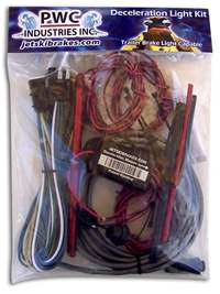
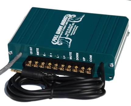
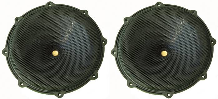
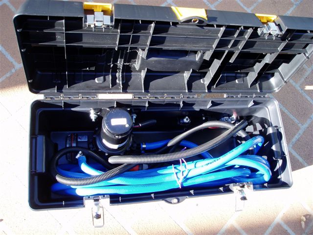
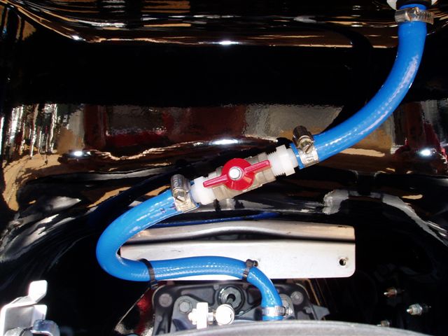
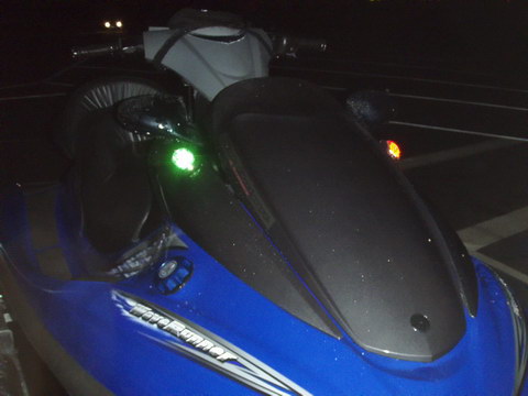
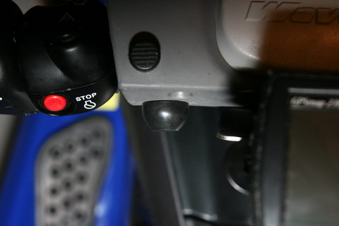
Full Wave Marine is the exclusive Australian Distributor for the Jet ski Brake Light Kits from PWC Industries and also the Waterproof Full Wave Audio kits designed for Personal Watercraft, Boats, All Terrain Vehicles and motorcycles. Jet Ski LED Brake Light Click here to BUY NOW at our on-line store *U.S. AND FOREIGN PATENTS PENDING* INSTRUCTIONS FOR INSTALLATION1. Locate a suitable position for mounting the module. It should be mounted above the waterline on a flat vertical surface anywhere from the middle of the ski to the rear, on the port (left side). Do not mount in the front. Thoroughly clean any dirt and oil from the surface. Remove backing from the module and affix to the surface. IMPORTANT – the module is to be mounted vertically (like a picture on a wall) Mount level with the waterline, making sure the arrow is pointing toward the front of the ski. Optional - Secure with two #6 stainless screws if you have the depth. Be careful not to go through the hull of your ski !!! 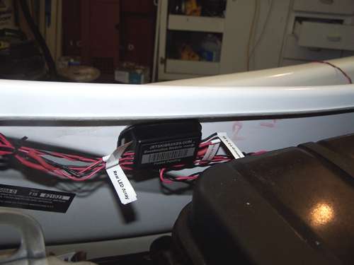 2. Using a test lamp, locate a 12v (+) source that is activated by your Lanyard, or key. This is because the Module zeros out G forces each time it is powered up. Usually a switched source for the positive lead, and a ground, can be found in the dash behind the instrument panel. If you are uncomfortable locating the correct wires, have a qualified person locate them for you. Splice, solder and heat shrink the 8’ 20 gauge wire at your power source and connect to the module. 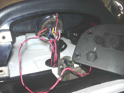 3. Remove the LED Array from the package. Carefully remove the end caps from the array tube. Slide the array out of the tube; place it and the end caps aside for later. 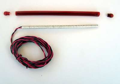 4. Determine a suitable location for mounting the array tube. The best location is up as high as possible so it remains visible to others. The LED array is flexible as shown. It may NOT be flexed in any other direction. If your mounting location is curved, gently heat the tube with a hair dryer to make it less rigid and pre-fit to your ski before affixing. This will ensure a tight fit and maintain appearance. Clean the location with the alcohol pad from the kit. Remove the protective backing from the array tube and affix to the location, making sure it’s centered. To prevent the ends from curling, drive a #2 stainless steel screw through the tube at each end. (Included) 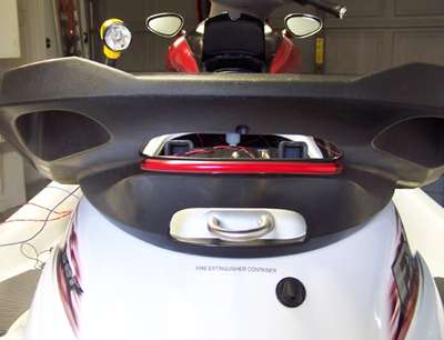 5. Drill a hole at one end of the tube. Make sure it is large enough to accommodate the wire, but small enough to be covered up by the end cap. 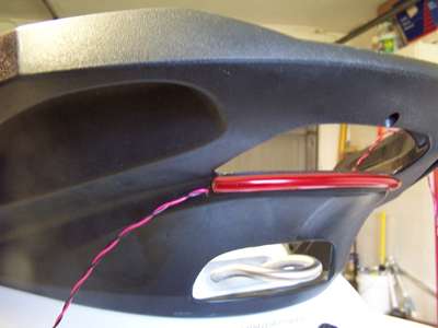 6. Carefully slide array into the tube and pull the wire through the hole. 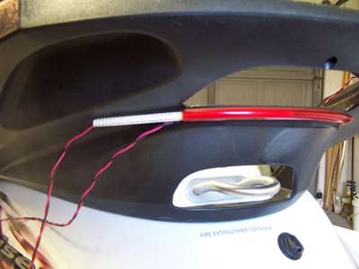 7. Using the tube of silicone provided, apply a small amount to the edge of the tube on both ends. 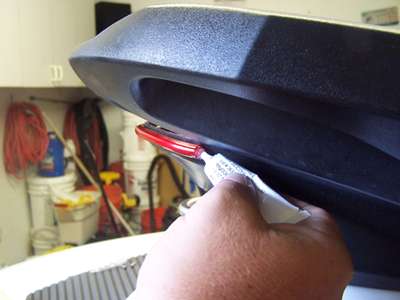 8. Look carefully at each end cap. One has a closed end; the other end cap is open which allows for the wire to pass through. Apply plenty of silicone to each end cap and carefully insert each one into the tube. Apply a small bead around the entire array tube where it contacts the surface and wipe off the excess. 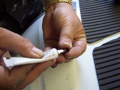 9. Drill an 11/32 hole in the dash where the dash mount LED will be visible. The LED is ribbed and designed to push in for a tight fit. It will be necessary to enlarge the hole slightly until it fits. This can be accomplished by running the drill bit in a circular motion. Try a little at a time until it can be pushed through and remain a snug fit. The dash LED is both a monitor, and also will blink rapidly if the rear array isn’t functioning. IMPORTANT - Check what’s behind your intended location BEFORE drilling! 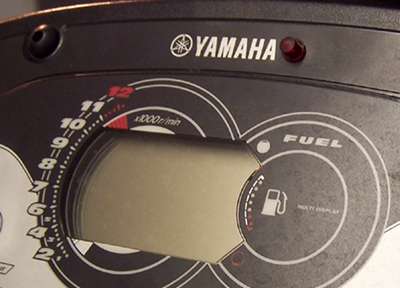 10. This is a look at the inside of your module. (models 811A & 811ATRL) In the event of a short, the fuse may be replaced with a .5 Amp fuse obtainable from any auto parts store. The module MUST be resealed with silicone if it has been opened for any reason. 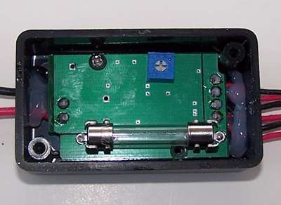 THIRD BRAKE LIGHT CAPABLE FEATURE 1. Choose a suitable location to mount the watertight socket. Here we chose a location under the front hood. Any location in the bow works fine. Drill a 9/16 hole, then continue to drill in a circular motion until you achieve a snug fit. IMPORTANT – Check the location BEFORE drilling. Remove the nut and rubber cap from the socket. Insert the socket from the backside of the hole, replace the rubber cap and tighten the nut. Run the wire to the Module; solder or crimp connection and heat shrink. Using the cable ties provided, secure the wiring. 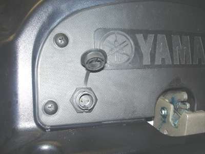 2. Plug the waterproof cable into the socket. (rotate slightly while pushing down, there is a notch which lines up the cable end so it is orientated correctly.) After the cable is plugged in, rotate the locking ring clockwise while pushing down slightly and the cable will be locked into the socket. To remove, rotate the locking ring counter clockwise and pull the cable out. When the cord is not plugged in, push the rubber cap in place to keep the socket clean. Route the cable to your trailer leaving some slack. 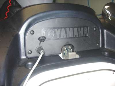 3. Drill holes large enough to accommodate the cable and route through your trailer frame to the tongue. Cut the cable to length and strip until all that remains is a red and black wire. The BLACK wire is Ground and should be spliced into the WHITE wire of your trailer, which is also Ground. This leaves the RED wire from the cable, which is to be connected to a 12 Volt power source from your vehicle’s brake lights. (Explained next) 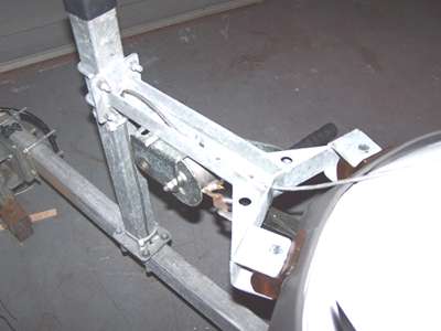 4. Decide whether you want to replace your existing trailer harness connectors, or merely add this 5-way connector. Replacement may limit your ability to tow other trailers, or others to tow yours, but shouldn’t be a factor if you just tow your own ski. There are numerous vehicle and trailer configurations and we presume you have the standard 4 way connectors now. Replace or splice into the current connectors, matching each color wire. This will leave a single BLUE wire left to connect. At the vehicle, use a test lamp to locate a 12v (+) wire that comes on when you press the brakes. (Make sure it does not blink with turn signals on) Attach the BLUE wire to the one you locate. At the Trailer, attach the BLUE wire from the new trailer connector to the RED wire of your new cable. 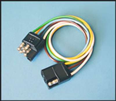 Solder and heat shrink all connections. Apply some WD-40 to each connector, the first few uses it will be tight. Test to make sure all lights are working before hitting the road. Specific Vehicle & Trailer wiring diagrams can easily be found on the Internet.
|
|
||||||||
 .
.